|
Previous Home Next
Design
4.1 Introduction
This chapter
gives details of the implementation design for the first stage (stages
described in chapter 3), which is the process after business class. After
formulating the requirements analysis, specifications of the proposed
application and design of a business class diagram, the details of
implementation design were prepared (along with experiments on various
available technologies). The implementation design was organised into five
main sections. The starting point was based on a simple 3D model, which would
then be replaced by the actual 3D model of the selected heritage structure
(i.e. St. George’s Church). It was decided to use an iterative implementation
process i.e. first design and implement a very basic application using the
above mentioned simple data file and then convert or add extra details to the
initial design, finally replacing this simple data with the actual data of
the selected heritage structure.
4.2. Design of
database (Top)
This section
describes how the first database was designed using a simple 3D model, which
was finally replaced by the model of the selected heritage structure. A
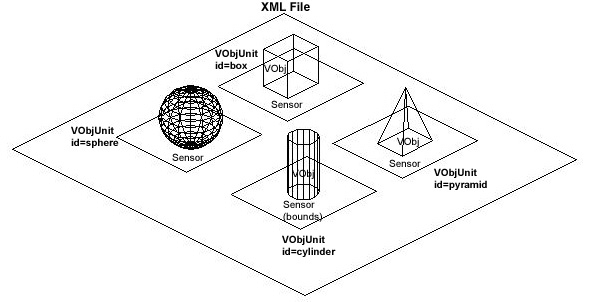
simple geometry file as shown in figure 4.1 was considered.
|
|
|
Figure
4.1: Geometry Representation in XML File
|
This XML file
can be explained as follows:
- An XML file for this application
consists of various visual objects identified by their ids (e.g.
VobjUnit id = box is one such visual object).
- Each id consists of a sensor area and
the actual geometry (i.e. Vobj). The sensor area is shown as a rectangle
in the figure for simplicity. This is actually defined as an invisible
box around the VObj in the virtual environment. The sensor (or “bounds”
in Java3D terminology) is used to sense if the navigator is inside or
near a particular area and extract the associated data.
- For each VobjUnit there is also a
detailed visual object (detVObj) associated. This is not shown in the
figure for simplicity. The purpose of this geometry is to give accurate
detail in terms of geometry for that particular VobjUnit.
- Thus the geometry of one VobjUnit
can be represented as “vObj + sensor + detVObj”.
- Similarly the entire geometry
based data can be represented in the XML file as
VObjUnit id = 1 + VObjUnit id = 2 + VObjUnit id = 3
and so on.
- The images data and the text data
for each VobjUnit were then added to complete the database and its
links. Thus, each VObj and each detVObj had a text file and an image
file associated in the VObjUnit.
- As the images were too many and
the size was big, it was decided to split the images into small and big
images to make the application display images quickly.
- Finally data that could not be
associated with any geometry (e.g. introduction text, introduction
image, text information and orthographic images unrelated to any of the
VobjUnits) was added to complete the database.
- This simple data file was then
used as a template for the actual data set of St. George’s church (see
Figure 4.2).
- A file format validity check
(signature) was introduced to identify that the correct format of XML
file is opened.
|
<?xml
version="1.0" encoding="UTF-8"?>
<StGeorges>
<validityCheck> n3d
</validityCheck>
<introText> introText.txt
</introText>
<introImage> introImage.jpg
</introImage>
<introBigImage>
introBigImage.jpg </introBigImage>
<!--Geometry and related
stuff-->
<vObjUnit id = "Tower Level
01">
<vObj> TowerLvl01.wrl
</vObj>
<vObjText>
TowerLvl01Text.txt </vObjText>
<vObjImage>
TowerLvl01Image.jpg </vObjImage>
<vObjBigImage>
TowerLvl01BigImage.jpg </vObjBigImage>
<detVObj>
TowerLvl01DetGeom.wrl </detVObj>
<detVObjText>
TowerLvl01DetText.txt </detVObjText>
<detVObjImage>
TowerLvl01DetImage.jpg </detVObjImage>
<detVObjBigImage>
TowerLvl01DetBigImage.jpg </detVObjBigImage>
<sensor>
TowerLvl01Sensor.wrl </sensor>
</vObjUnit>
<vObjUnit id = "Tower Level
02">
<vObj> TowerLvl02.wrl
</vObj>
<vObjText>
TowerLvl02Text.txt </vObjText>
<vObjImage>
TowerLvl02Image.jpg </vObjImage>
<vObjBigImage>……………………..
</vObjUnit>
……………
………….
<!--Orthographic
projection images-->
<orthoImage id = "Site
Plan">
<image> siteplan.jpg
</image>
<bigImage>
bigSitePlan.jpg </bigImage>
</orthoImage>
<orthoImage id =
"Plan">
<image> plan.jpg
</image>
<bigImage> bigPlan.jpg </bigImage>
</orthoImage>
……………
………….
<!--Text
data by categories-->
<categorizedText>
<bldgName> bldgName.txt
</bldgName>
<address> address.txt
</address>
<cartogRef>
cartographicRef.txt </cartogRef>
<natGrid>
catText\natGrid.txt </natGrid>
<bldgType> bldType.txt
</bldgType>
<bldgCat>
bldgCategory.txt </bldgCat>
<style>…………..
</categorizedText>
</StGeorges>
|
|
Figure
4.2: Final XML File (in fragments)
|
4.3 GUI
design of Application (Top)
Chapter 3 shows
the GUI design of a future application (incorporating all the advanced
features). This section shows the different alternatives of GUI’s that were
designed for implementation of the first stage of the application. The
following alternatives were devised and revised following the principles of
graphic user interface design:
First attempt:
|
Title Bar
|
|
Menu Bar
|
|
Tool Bar
|
|
Examination Viewport
|
Navigation Viewport
|
|
Image Viewport
|
|
Text Viewport
|
|
This was the
first design for the first stage of the proposed application. The screen
size was fixed at 800 x 600 as most of the users are comfortable with this
resolution and it is the least standard used by all the monitors. The
problems that were encountered with this design were:
1.
Small and elongated area for the
text viewport in prime estate.
2.
Examination viewport is expected
to be the most interacted with and yet it was not located in the lower
right area.
|
Second
attempt:
|
Title Bar
|
|
Menu Bar
|
|
Tool Bar
|
|
Navigation Viewport
|
Examination Viewport
|
|
Image Viewport
|
|
Text Viewport
|
|
This was the
second design for the first stage of the proposed application. The screen size
had to be kept the same hence this design provided no solutions. The
problems that were encountered with this design were:
1.
Small and elongated area for the
text viewport in prime estate.
2.
Navigation Viewport is also
expected to be the most interacted with and it was not located in the lower
right area.
|
Final attempt:
|
Title Bar
|
|
Menu Bar
|
|
Tool Bar
|
|
Text Viewport
|
Navigation Viewport
|
|
Examination Viewport
|
Image Viewport
|
|
This was the
final and most satisfactory design for the first stage of the proposed
application while keeping the screen size.
1.
Text viewport was better organised
and located on the left side.
2.
The most interacted viewports
(Navigation, Examination and Images) were appropriately located together on
the right side.
|
Function of
each area is described as follows:
- Title Bar shows the Application
Icon and the Application Name (ARCHERR). When an appropriate data file
is opened, the file name is added to the Application name.
- Menu Bar gives access (with
standard keyboard shortcuts) to various features of the application.
- Tool Bar gives alternative access
to various features of the application along with additional toggle
actions.
- Text viewport shows the relevant
information as the user navigates or double clicks to find more
information.
- Navigation viewport allows the
user to navigate in the virtual environment of the opened heritage site
using the keyboard.
- Examination viewport allows the
user to examine selected objects (from the Navigation viewport) by
rotating, translating and zooming into the object using the mouse. The
importance of the examination should not be undermined as depending upon
the design of the database, the minutest of the details with complete
accuracy can be viewed and examined in isolation but with reference to
the navigation viewport (e.g. In the St. George’s Church database, the
buttress is a very small part of the entire structure and since the data
is provided in the database, it can be double clicked in the navigation
viewport to open a detailed version for examination in the examination
viewport).
- Image viewport shows the relevant
real world pictures while navigating or when double clicked on a
particular object in the Navigation viewport or the examination
viewport.
Note: It was decided not to use mouse
for navigation as most mouse functions were already being used for obvious
purposes like double clicking, rotating and finding distances. To separate
out the functionality and avoid confusion, keyboard navigation was
implemented. This proved to be advantageous as keyboard navigation is far
more accurate than mouse navigation besides allowing multiple functions (see
appendix 3 User Manual No.4 and No.10 for details on keyboard and mouse
functions respectively).
4.4 Design of user actions and corresponding application
actions (Top)
This section
gives a table of refined actions that were expected to be performed by the
user. This section was felt to be of utmost importance before the beginning
of the implementation process and was modified iteratively due to constraints
dictated by JDK1.3.0 API, the usability issues, and hardware issues.
|
|
User Action
|
Application Action
|
|
1.
|
User opens file (of type *.xml)
|
- Remove all
existing geometries from the Navigation viewport (including sensors).
- Extract
<vObj> and <sensor> data (of type *.vrml) for each
<vObjUnit> and display the complete virtual environment in the
navigation viewport.
- Remove the
data from the Text viewport if any.
- Extract
<introText> data (of type *.txt) and display the text in the text
viewport.
- Remove the
data from the Images viewport if any.
- Extract
<introImage> data (of type *.jpg) and display the image in the images
viewport.
- Remove all
data from the Examination viewport.
- Create a
list of all images in the database for reference.
|
|
2.
|
User enters a sensor area while
navigating.
|
- Identify
<vObjUnit> for sensor area the user is in.
- Clear text
and images viewport.
- Extract
<vObjText> data for that <vObjUnit> and display it in the text
viewport (if “show text details automatically” is set to “on”).
- Extract
<vObjImage> data for that <vObjUnit> and display it in the
images viewport (if “show images automatically” is set to “on”).
|
|
3.
|
User double clicks on a part of model
in the navigation viewport.
|
- Identify
<vObjUnit> for part of the model the user has double clicked.
- Clear
examination viewport.
- Extract
<detVObj> data (of type *.vrml) for that <vObjUnit> and display
it in the examination viewport.
- Clear
Images viewport.
- Extract
<vObjImage> data (of type *.jpg) for that <vObjUnit> and
display it in the Images viewport.
- The user
can then rotate, translate, zoom into the detailed model.
|
|
5.
|
User selects “Find Distance” option.
|
- Turn off
double clicking.
|
|
|
User selects first point using the
mouse.
|
- Snap to
the nearest vertex of the geometry and display the selected point in the
navigation viewport.
- Extract and
store the co-ordinates of this point.
|
|
|
User selects second point using the
mouse.
|
- Snap to
the nearest vertex of the geometry and display the selected point in the
navigation viewport.
- Extract
and store the co-ordinates of this point.
- Calculate
distances in ‘x’, ‘y’ and ‘z’ axes and actual distance and display the
result through a dialog box.
- Ask the
user whether the selection points should be cleared and remove if user
answers “yes”.
|
|
6.
|
User double clicks on the detailed
model in the examination viewport.
|
- Identify
<vObjUnit> for the detailed model the user has double clicked.
- Clear text
and images viewport.
- Extract
<detVObjText> data for that <vObjUnit> and display it in the text
viewport (override “show text details automatically” setting).
- Extract
<detVObjImage> data for that <vObjUnit> and display it in the
images viewport (override “show images automatically” setting).
|
|
7.
|
User selects “Show Category Text”
option.
|
- Ask the
user to select a category of textual information through another window.
|
|
|
User selects and clicks “Show Result”
button.
|
- Display
the relevant text after extracting from <categorizedText>.
|
|
8.
|
User selects “View All Images” option.
|
- Extract
all <vObjImage>
- Extract
all <detVObjImage>
- Extract
all <OrthoImages>
- Create
thumbnail images and display them in a tabbed pane for all three.
|
|
9.
|
Clear All
|
- Clear the
examination viewport, images viewport and text viewport.
|
|
|
Clear examination viewport
|
- Clear the
examination viewport.
|
|
|
Clear images viewport
|
- Clear the
imagesviewport.
|
|
|
Clear text viewport
|
- Clear the
text viewport.
|
|
10.
|
User double clicks on text viewport
|
- Open a new
window
- Display the
text from the text viewport.
|
|
11.
|
User double clicks on image viewport
|
- Open a new
window
- Display a
bigger image of the image currently in the images viewport.
|
|
12.
|
User Clicks on Help Button
|
- Open the default
browser and display the html version of help.
|
|
13.
|
User Clicks on Quit Button
|
- Clear the
navigation, examination and images viewports and exit the application.
|
|
14.
|
User Clicks on About button
|
- Open a
dialog box displaying information about the application.
|
|
15.
|
User Clicks on Contact button
|
- Open the
default mailer program with the creators email address already filled in.
|
|
Table
4.1 User Actions and Application Actions
|
4.5 Implementation
Classes (Top)
This section
enumerates the final classes that were used in the implementation of the
application.
Figure 4.3
shows a class diagram of the implementation. The relationship of Action
classes and helper classes is not shown to avoid complexity and confusion.
Also many relationships exist between the multi functional ToolBar with other
classes (similarly for MenuBar) but only the important ones are shown in this
diagram. Description of each class is given for clarification.
|
|
|
Figure
4.3: Class Diagram showing important relations
|
The classes
were iteratively modified and new classes were added during the
implementation stage and were logically divided into the following parts:
Main Class:
1.
Archerr
This class
contains the main method. It first creates a SplashWindow displaying the
splash image and then constructs the GUI classes of the ArchRefFrame class.
GUI
Classes:
1.
ArchRefFrame
This class creates the first GUI using the following components
when the application is started for the first time (component classes
underlined in figure 4.3):
a.
XscrollPane: Allows scrolling of
XTextArea forming the Text Viewport.
b.
NaviPanel: Creates the Navigation
Viewport by adding an instance Canvas3D.
c.
ExamPanel: Creates the Examination
Viewport by adding an instance of Canvas3D.
d.
ImagePanel: Creates the Images
Viewport.
e.
XMenuBar: Creates the MenuBar.
f.
XtoolBar: Creates the ToolBar.
2.
XtextFrame
This class is instantiated only when the mouse is double clicked
inside the XtextArea and there is text displayed in the XtextArea. This class
creates a new window displaying the text from the XtextArea.
3.
BigImageFrame
This class is instantiated only when the mouse is double clicked
inside the ImagePanel and there is image displayed in the ImagePanel. This
class creates a new window with BigImagePanel and displays a bigger image of
the one displayed in the ImagePanel. This class is also instantiated when
mouse is clicked on the thumbnail images displayed in the AllImageFrame.
4.
CatFrame
This class is instantiated when the Cat. Button in the XToolBar or
the XMenuBar is clicked. This class uses checkboxes for selection of
categorised text and display the selected text in a scrollable TextArea. This
class is instantiated only when a data file has been opened.
5.
AllImageFrame
This class is instantiated when the Thumb. Button in the XToolBar
or the XMenuBar is clicked. This class uses a TabbedPane to display images in
three categories:
a.
AllImagePanel displays thumbnail
images of all main images.
b.
AllDetImagePanel displays thumbnail
images of all close up images.
c.
AllOrthoImagePanel displays
thumbnail images of all orthographic drawing images.
6.
FeedBack
This class is used to display appropriate message in a new window
on top of the NaviPanel for any long actions. This class is used in three
places (a) when mouse is double clicked in the navigation viewport to load
the corresponding detailed part of the structure in the Examination Viewport
(b) when a data file is in the process of being opened and (c) while creating
thumbnail images to be displayed in AllImageFrame.
Helper
Classes:
1.
XMLFilter
This class is used to show only XML files in the JFileChooser.
2.
XMLReader.java (Static)
This class provides the data store (current file, image filenames
etc) during the use of the application and provides accessor methods to read
any information from the data file under consideration.
Action
Classes:
- AboutAction: Used to display a dialog
box (with the information about the application) when the “About” button
in XtoolBar or XMenuBar is clicked.
- AllImAction: Used to instantiate
the AllImageFrame when the “Thumb.” button in XtoolBar or XMenuBar is
clicked.
- BigDetImageAction: Used to display
a big image when a detailed thumbnail image is clicked.
- BigImageAction: Used to display a
big image when a main thumbnail image is clicked.
- BigOrthoImageAction: Used to
display a big image when an ortho thumbnail image is clicked.
- CatAction: Used to instantiate the
CatFrame when the “Cat.”button in XtoolBar or XMenuBar is clicked.
- ClearExamAction: Removes all the
visual objects from the ExamPanel after displaying a confirmation dialog
box.
- ClearImageAction: Removes the
image from the ImagePanel after displaying a confirmation dialog box.
- ClearTextAction Removes the text
from the XTextArea after displaying a confirmation dialog box.
- ClearAllAction: Executes
ClearExamAction, ClearImageAction and ClearTextAction together after
displaying a confirmation dialog box.
- ClickAction: Enables and disables
identification of clickable objects in the NaviPanel.
- DistAction: Enables the distance
finding facility in the NaviPanel.
- ImagesToggleAction: Enables or
disables automatic display of images in the ImagePanel while navigating
in the NaviPanel.
- TextToggleAction: Enables or
disables automatic display of text in the XTextArea while navigating in
the NaviPanel.
- TextBoundsBehavior: Used to get
relevant text when automatic text display is switched on.
- ImagesBoundsBehavior: Used to get
relevant image when automatic image display is switched on.
- OpenAction: Instantiates the
JFileChooser to allow selection of data file for loading when “Open”
button in XtoolBar or XMenuBar is clicked.
- QuitAction: Closes the application
after freeing up resources when “Quit” button in XtoolBar or XMenuBar is
clicked.
- WebAction: Used to open the
default browser or the default mailer client when the “Manual” button or
the “Contact” button button in XtoolBar or XMenuBar is clicked.
Previous Home Next
|